-
- Experimental sand grinder
- Experimental Sand Grinder NT-V Series
- Experimental Sand Grinder NT-VS Series
- Experimental Sand Grinder LSM Series
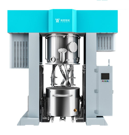
Sand mill is a commonly used grinding equipment mainly used for wet grinding of chemical liquid products. According to its performance, it can be roughly divided into horizontal sand mill, basket sand mill, vertical sand mill, etc. Today, the editor will mainly introduce the purpose and design principles of sand mills, hoping to help everyone.
Application of sand grinding machine
Compared with grinding equipment such as ball mills, roller mills, and colloid mills, sand mills have the advantages of strong production efficiency, strong continuity, low cost, and high product fineness. There are significant differences in process conditions, and the fineness requirements can be adjusted and classified by adding or subtracting appropriate grinding media. Generally, vertical sand mill, horizontal sand mill, basket type sand mill, double cone bar type sand mill and nano level horizontal sand mill are common. Except for vertical sand mill, ordinary 2-3/3-4mm glass bead are used, 0.8-2.4mm zirconia beads are used for other equipment.
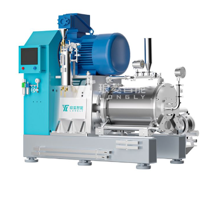
Design principle of sand mill
The sand mill adopts an eccentric disc grinding structure and is arranged in a certain order. This system overcomes the disadvantage of uneven distribution of grinding media in traditional grinding machines, allowing for greater energy transfer of the grinding media. It adopts a dual end face forced cooling mechanical seal, which has good sealing effect and reliable operation. The separation system adopts a large flow LDC dynamic grid gap separator, which will not cause blockage of the discharge port under high flow conditions and has a flow area of, The gap range is 0.05-2.0mm, and grinding media above 0.1mm can be used. The horizontal sanding mill adopts the closed design of eccentric disc grinding chamber. The grinding disc is installed on the mixing shaft in a certain order, which overcomes the shortcomings of the traditional horizontal sanding mill, such as uneven distribution of grinding media and poor particle size distribution after grinding. Materials enter the grinding chamber under the action of the feed pump. The inlet is designed at the end of the drive connecting flange. The direction of the material flow and the mechanical bearing are opposite to the bottom end, which greatly reduces the bearing pressure of the mechanical seal, Extending its service life, during the high-speed operation of the eccentric disc of the mixing shaft, the mixture of materials and grinding media undergoes efficient relative motion. As a result, the solid particles of the material are effectively dispersed, sheared, and ground, and after passing through the dynamic large flow rotor gap separation filter, they enter the product. Depending on the grinding process of the product, independent batch cycle grinding and series grinding processes can be used.


 Home
Home